We provide you with the superior quality Pipe Repair Clamps manufacturer in India. A leaky water or gas pipe can cause significant difficulties, so it should be repaired as soon as possible but in a safe and long-lasting manner to prevent additional water or gas loss. Our stainless steel pipe fixing clamp can be used to fix broken or damaged pipelines permanently.
Pipe leak clamp is a type of device used to repair pipe clamp hydraulic and seal a leaky pipeline. This is a long-term mending method. This procedure can be used to repair locally corrupted, damaged, and cracked pipes.
Pipe repair clamps are designed and manufactured by our organization. Our pipeline clamps may be customized to fit a variety of dimensions and pressure ratings. Tie-in, hot tapping, repair, leak sealing, and reinforcing are just a few of the uses of hydraulic pipe clamp. In our high-tech machine shop, we precisely machine our pipe repair clamps and hydraulic pipe clamp manufacturer in India.
The transportation and transfer of fluids from wellheads to offshore process system pipework and pipelines to refining facilities are critical to the oil and gas industry’s safety, efficiency, and economic sustainability.
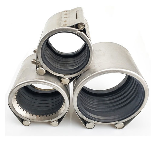
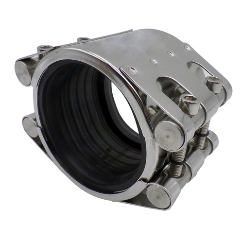
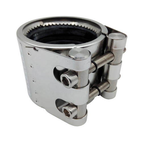
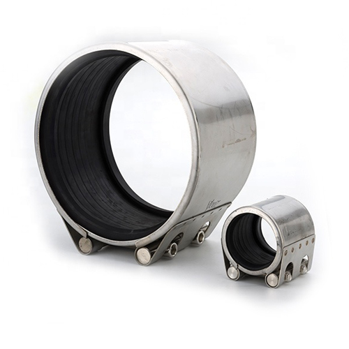
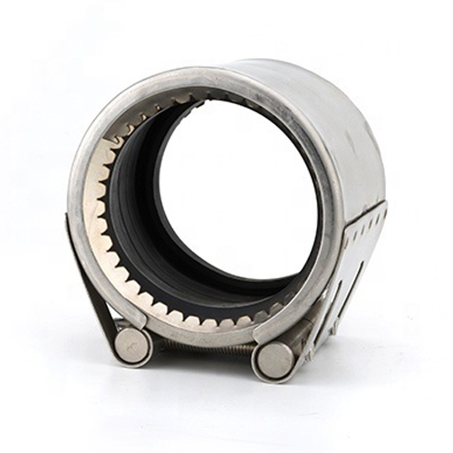
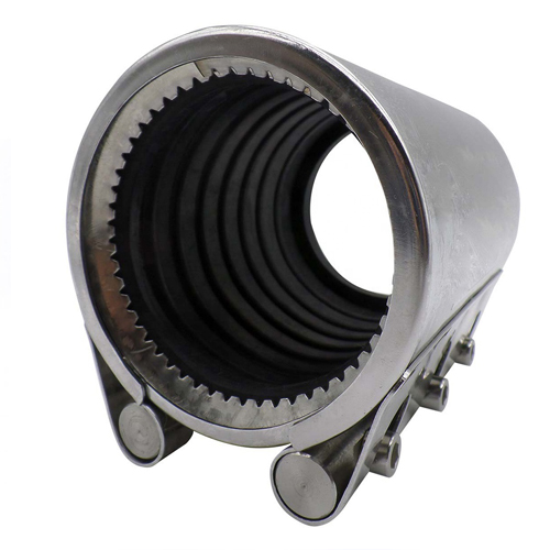
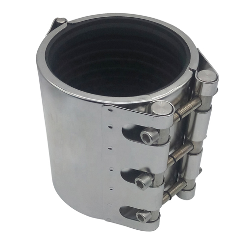
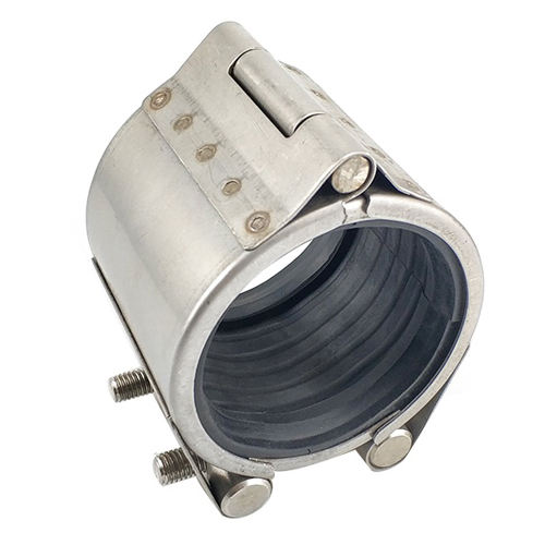
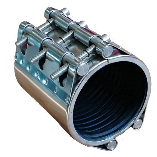
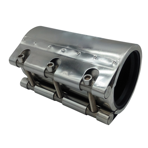
The high pressure pipe repair clamps hydraulic are essentially a pre-rolled stainless steel plate with a rubber lining secured with welded bolts and nuts. The clamp fasteners‘ tensile strain is translated to radial pressure on the rubber liner, ensuring a secure seal.
• Lightweight strap clamp for repair or intervention in a specific area
• Self-energised pipe-to-pipe sealing
• Installation is quick and straightforward.
• The low-profile design enables installation in tight spaces.
• Repair (Blind), Hot Tap (Flanged), or Encapsulation (Capped) seal housings are available.
• Low and high-pressure applications are both possible.
• Their design allows components to be reused for different pipe geometries.
• Sealing material is provided according to the application (NBR, HNBR, Viton, HPU)
• Carbon steel that complies with NACE standards is standard; alternative materials are available upon request.
• Single or multiple seal configurations are available.
We have a wide range of superior quality Pipe Repair Clamps Manufacturer in India. We have all thermoplastic piping materials and working successfully for over 60 years.
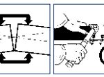
Repairing a leaking pipe Clamps can be used in a variety of scenarios on gas or water pipes where there is a leak, and immediate repair is required:
• Holes in pipes made of asbestos cement, steel, or cast iron
• Asbestos-cement and cast-iron pipe breaks
• Asbestos cement, steel, cast iron, and PVC pipe cracks
• Damage caused by a service crane or branching portions that have been broken off
• Leaks caused by corrosion
Pipeline and process pipe inspections regularly can reveal faults or leaks that require modification or repair.
Clients and our organization work together to ensure that the unique requirements of any replacement or repair solution are correctly understood and risk assessed. The solutions are designed to meet the system’s rigorous design and operating parameters.
Our pipe repair clamps manufacturer is designed to fit a wide range of applications for onshore, topsides, and subsea installation. Our cutting-edge repair and maintenance solutions help operators prevent or decrease downtime while also lowering risk and spending.
Our company offers various caisson handling equipment for securing and recovering broken or superfluous caissons safely and efficiently. Internal and external lifting tools are available in various sizes to allow for the safe and controlled removal of caissons.
| OUR PERFORMANCE | YOUR ADVANTAGE |
| COMPATIBILITY | STOCK REDUCTION |
| SYSTEM INDEPENDENCE | FREE CHOICE OF PIPE SUPPLIER |
| RELIABILITY | REDUCTION OF REWORK |
| EFFICIENCY | RAPID INSTALLATION TIMES |
| SAFETY | PERSONAL AND ENVIRONMENTAL PROTECTION |
| SERVICE | MANUFACTURER’S TECHNICAL SUPPORT |
| QUALITY | CONSISTENT QUALITY ASSURED |
The progressive sealing effect is a unique and patented feature of the PETRONTHERMOPLAST gasket.

PETRONTHERMOPLAST pipe couplings are used on conventional plain ended pipes without pipe end preparation being necessary.
The progressive anchoring effect of all GRIP products is a unique and patented feature:

The sealing and anchoring functions are independent of one another in PETRONTHERMOPLAST pipe couplings.
AnchoringThe spring effect of the housing and the anchoring ring result in a flexible gripping connection. The housing which bridges the pipe ends imparts no forces and thereby keeps the stress on the various components to a minimum. The pipework is therefore not rigid but is flexible at every joint.
Sealing
The gasket is positioned on the surface of the pipe and enables the pipe ends to move freely.

| Components / Materials | W1 | W2 | W4 | W5 |
| Casing | AISI 316 L | AISI 316 L or similar | ||
| Bolts | AISI 4135 | A4 – 80 | ||
| Bars | AISI 12L14 galvanised | AISI 316 L or similar | ||
| Anchoring rings | AISI 301 | AISI 301 | ||
| Strip insert (option) | AISI 316 L or similar / PVDF | AISI 316 L or similar / PVDF |
| Sealing sleeve EPDM |
Temp.: Medium: |
-30°C up to +100°C all qualities of water, waste water, air, solids and chemical products |
| Sealing sleeve NBR |
Temp.: Medium: |
-20°C up to +80°C water, gas, oil, fuel and other hydrocarbons |

| OD [mm] |
Clamping range [mm] |
PN [bar] |
PN [bar] |
B [mm] |
C [mm] |
DV [mm] |
X [mm] |
R without strip insert [mm] |
R with strip insert [mm] |
Torque rate [Nm] |
Allen head [mm] |
Thread M… |
| 30.0 | 29.5 – 30.5 | 67 | 16 | 46/67 | 18 | 47 | 56 | 5 | 5 | 10 | 6 | 8 |
| 33.7 | 33.2 – 34.2 | 62 | 16 | 46/67 | 18 | 52 | 63 | 5 | 5 | 10 | 6 | 8 |
| 38.0 | 37.5 – 38.5 | 58 | 16 | 61 | 19 | 58 | 73 | 5 | 5 – 10 | 15 | 6 | 8 |
| 42.4 | 41.9 – 42.9 | 53 | 16 | 61 | 20 | 62 | 76 | 5 | 5 – 10 | 15 | 6 | 8 |
| 44.5 | 44.0 – 45.0 | 48 | 16 | 61 | 20 | 64 | 80 | 5 | 5 – 10 | 15 | 6 | 8 |
| 48.3 | 47.8 – 48.8 | 44 | 16 | 61 | 20 | 68 | 83 | 5 | 5 – 10 | 15 | 6 | 8 |
| 54.0 | 53.5 – 54.5 | 39 | 16 | 77 | 38 | 74 | 89 | 5 | 5 – 15 | 15 | 6 | 8 |
| 57.0 | 56.4 – 57.6 | 37 | 16 | 77 | 32 | 77 | 92 | 5 – 10 | 5 – 25 | 15 | 6 | 8 |
| 60.3 | 59.7 – 60.9 | 37 | 16 | 77 | 32 | 82 | 95 | 5 – 10 | 5 – 25 | 15 | 6 | 8 |
| 63.5 | 62.9 – 64.1 | 37 | 16 | 77 | 32 | 84 | 98 | 5 – 10 | 5 – 25 | 15 | 6 | 8 |
| 73.0 | 72.2 – 73.8 | 56 | 16 | 94 | 39 | 95 | 117 | 5 – 10 | 5 – 25 | 35 | 8 | 10 |
| 76.1 | 75.3 – 76.9 | 56 | 16 | 94 | 39 | 100 | 117 | 5 – 10 | 5 – 25 | 35 | 8 | 10 |
| 84.0 | 83.2 – 84.8 | 45 | 16 | 94 | 39 | 112 | 123 | 5 – 10 | 5 – 25 | 35 | 8 | 10 |
| 88.9 | 88.0 – 89.8 | 41 | 16 | 94 | 39 | 117 | 123 | 5 – 10 | 5 – 25 | 35 | 8 | 10 |
| 104.0 | 103.0 – 105.0 | 37 | 16 | 94 | 39 | 133 | 151 | 5 – 10 | 5 – 25 | 35 | 8 | 10 |
| 108.0 | 106.9 – 109.1 | 35 | 16 | 94 | 39 | 133 | 151 | 5 – 10 | 5 – 25 | 35 | 8 | 10 |
| 114.3 | 113.2 – 115.4 | 34 | 16 | 94 | 39 | 139 | 157 | 5 – 10 | 5 – 25 | 35 | 8 | 10 |
| 129.0 | 127.7 – 130.3 | 33 | 16 | 108 | 43 | 160 | 182 | 5 – 15 | 5 – 25 | 60 | 10 | 12 |
| 133.0 | 131.7 – 134.3 | 33 | 16 | 108 | 43 | 160 | 182 | 5 – 15 | 5 – 25 | 60 | 10 | 12 |
| 139.7 | 138.3 – 141.1 | 32 | 16 | 109 | 43 | 168 | 191 | 5 – 15 | 5 – 25 | 60 | 10 | 12 |
| 154.0 | 152.5 – 155.5 | 32 | 16 | 109 | 51 | 186 | 210 | 5 – 15 | 5 – 25 | 60 | 10 | 12 |
| 159.0 | 157.4 – 160.6 | 31 | 16 | 109 | 43 | 187 | 210 | 5 – 15 | 5 – 25 | 60 | 10 | 12 |
| 168.3 | 166.6 – 170.0 | 29 | 16 | 109 | 43 | 200 | 220 | 5 – 15 | 5 – 25 | 60 | 10 | 12 |
| 219.1 | 216.9 – 221.3 | 26 | 16 | 150 | 60 | 259 | 288 | 5 – 15 | 5 – 35 | 100 | 14 | 16 |
| Components / Materials | W1 | W2 | W4 | W5 |
| Casing | AISI A738, hot-dip galvanised | |||
| Bolts | AISI 4135 | |||
| Bars | AISI 12L14, galvanised | |||
| Anchoring rings | AISI 301 | |||
| Strip insert (option) | AISI 316 L or similar / PVDF |
| Sealing sleeve EPDM |
Temp.: Medium: |
-20°C up to +100°C all qualities of water, waste water, air, solids and chemical products |
| Sealing sleeve NBR |
Temp.: Medium: |
-20°C up to +80°C water, gas, oil, fuel and other hydrocarbons |

| OD [mm] |
Clamping range [mm] |
PN [bar] |
PN [bar] |
B [mm] |
C [mm] |
DV [mm] |
X [mm] |
R without strip insert [mm] |
R with strip insert [mm] |
Torque rate [Nm] |
Allen head [mm] |
Thread M… |
| 180.0 | 178.0 – 182.0 | 29 | 16 | 148 | 67 | 225 | 256 | 5 – 15 | 5 – 35 | 150 | 17 | 20 |
| 193.7 | 192.0 – 195.5 | 29 | 16 | 148 | 67 | 239 | 270 | 5 – 15 | 5 – 35 | 150 | 17 | 20 |
| 200.0 | 198.0 – 202.0 | 28 | 15 | 148 | 67 | 245 | 276 | 5 – 15 | 5 – 35 | 180 | 17 | 20 |
| 206.0 | 204.0 – 208.0 | 28 | 15 | 148 | 67 | 251 | 282 | 5 – 15 | 5 – 35 | 180 | 17 | 20 |
| 244.5 | 242.0 – 247.0 | 27 | 14 | 148 | 67 | 290 | 330 | 5 – 15 | 5 – 35 | 180 | 17 | 20 |
| 267.0 | 264.5 – 269.5 | 24 | 12 | 148 | 67 | 312 | 352 | 5 – 15 | 5 – 35 | 180 | 17 | 20 |
| 273.0 | 270.5 – 275.5 | 21 | 12 | 148 | 67 | 318 | 359 | 5 – 15 | 5 – 35 | 180 | 17 | 20 |
| 323.9 | 320.5 – 327.0 | 18 | 10 | 148 | 67 | 369 | 411 | 5 – 15 | 5 – 35 | 230 | 17 | 20 |
| 355.6 | 352.0 – 359.0 | 17 | 8 | 148 | 67 | 401 | 444 | 5 – 15 | 5 – 35 | 230 | 17 | 20 |
| 406.4 | 402.5 – 410.5 | 14 | 8 | 148 | 67 | 451 | 494 | 5 – 15 | 5 – 35 | 230 | 17 | 20 |
| 457.2 | 452.5 – 462.0 | 8 | 6 | 148 | 67 | 502 | 546 | 5 – 15 | 5 – 35 | 250 | 17 | 20 |
| 508.0 | 503.0 – 513.0 | 6 | 5 | 148 | 67 | 553 | 598 | 5 – 15 | 5 – 35 | 250 | 17 | 20 |
| 558.8 | 554.0 – 564.0 | 6 | 4.5 | 148 | 67 | 604 | 649 | 5 – 15 | 5 – 3 | 5 300 | 17 | 20 |
| 609.6 | 604.5 – 614.5 | 5 | 4 | 148 | 67 | 655 | 701 | 5 – 15 | 5 – 35 | 300 | 17 | 20 |
| Components / Materials | W1 | W2 | W4 | W5 |
| Casing | AISI 316 L | AISI 316 L or similar | ||
| Bolts | AISI 4135 | A4 – 80 | ||
| Bars | AISI 12L14, galvanised | AISI 316 L or similar | ||
| Anchoring rings | AISI 301 | AISI 301 | ||
| Strip insert (option) | AISI 316 L or similar / PVDF | AISI 316 L or similar / PVDF |
| Sealing sleeve EPDM |
Temp.: Medium: |
-30°C up to +100°C all qualities of water, waste water, air, solids and chemical products |
| Sealing sleeve NBR |
Temp.: Medium: |
-20°C up to +80°C water, gas, oil, fuel and other hydrocarbons |

| OD [mm] |
Clamping range [mm] |
PN [bar] |
PN [bar] |
B [mm] |
C [mm] |
DV [mm] |
X [mm] |
R without strip insert [mm] |
R with strip insert [mm] |
Torque rate [Nm] |
Allen head [mm] |
Thread M… |
| 30.0 | 29.5 – 30.5 | 67 | 16 | 46/67 | 18 | 57 | 61 | 5 | 5 | 10 | 6 | 8 |
| 33.7 | 33.2 – 34.2 | 62 | 16 | 46/67 | 18 | 62 | 68 | 5 | 5 | 10 | 6 | 8 |
| 38.0 | 37.5 – 38.5 | 58 | 16 | 71 | 19 | 68 | 78 | 5 | 5 – 10 | 15 | 6 | 8 |
| 42.4 | 41.9 – 42.9 | 53 | 16 | 71 | 20 | 72 | 81 | 5 | 5 – 10 | 15 | 6 | 8 |
| 44.5 | 44.0 – 45.0 | 48 | 16 | 71 | 20 | 74 | 85 | 5 | 5 – 10 | 15 | 6 | 8 |
| 48.3 | 47.8 – 48.8 | 44 | 16 | 71 | 20 | 78 | 88 | 5 | 5 – 10 | 15 | 6 | 8 |
| 54.0 | 53.5 – 54.5 | 39 | 16 | 87 | 38 | 84 | 94 | 5 | 5 – 15 | 15 | 6 | 8 |
| 57.0 | 56.4 – 57.6 | 37 | 16 | 87 | 32 | 87 | 97 | 5 – 10 | 5 – 25 | 15 | 6 | 8 |
| 60.3 | 59.7 – 60.9 | 37 | 16 | 87 | 32 | 87 | 100 | 5 – 10 | 5 – 25 | 15 | 6 | 8 |
| 63.5 | 62.9 – 64.1 | 37 | 16 | 87 | 32 | 94 | 103 | 5 – 10 | 5 – 25 | 15 | 6 | 8 |
| 76.1 | 75.3 – 76.9 | 56 | 16 | 110 | 39 | 110 | 122 | 5 – 10 | 5 – 25 | 35 | 8 | 10 |
| 84.0 | 83.2 – 84.8 | 45 | 16 | 110 | 39 | 122 | 128 | 5 – 10 | 5 – 25 | 35 | 8 | 10 |
| 88.9 | 88.0 – 89.8 | 41 | 16 | 110 | 39 | 127 | 128 | 5 – 10 | 5 – 25 | 35 | 8 | 10 |
| 104.0 | 103.0 – 105.0 | 37 | 16 | 110 | 39 | 143 | 156 | 5 – 10 | 5 – 25 | 35 | 8 | 10 |
| 108.0 | 106.9 – 109.1 | 35 | 16 | 110 | 39 | 143 | 156 | 5 – 10 | 5 – 25 | 35 | 8 | 10 |
| 114.3 | 113.2 – 115.4 | 34 | 16 | 110 | 39 | 149 | 162 | 5 – 10 | 5 – 25 | 35 | 8 | 10 |
| 129.0 | 127.7 – 130.3 | 33 | 16 | 124 | 43 | 170 | 187 | 5 – 15 | 5 – 25 | 60 | 10 | 12 |
| 133.0 | 131.7 – 134.3 | 33 | 16 | 125 | 43 | 170 | 187 | 5 – 15 | 5 – 25 | 60 | 10 | 12 |
| 139.7 | 138.3 – 141.1 | 32 | 16 | 125 | 43 | 178 | 196 | 5 – 15 | 5 – 25 | 60 | 10 | 12 |
| 154.0 | 152.5 – 155.5 | 32 | 16 | 125 | 51 | 196 | 215 | 5 – 15 | 5 – 25 | 60 | 10 | 12 |
| 159.0 | 157.4 – 160.6 | 31 | 16 | 125 | 43 | 197 | 215 | 5 – 15 | 5 – 25 | 60 | 10 | 12 |
| 168.3 | 166.6 – 170.0 | 29 | 16 | 125 | 43 | 210 | 225 | 5 – 15 | 5 – 25 | 60 | 10 | 12 |
| 219.1 | 216.9 – 221.3 | 26 | 16 | 166 | 60 | 269 | 293 | 5 – 15 | 5 – 35 | 100 | 14 | 16 |
| Components / Materials | W1 | W2 | W4 | W5 |
| Casing | AISI 316 L / LDX 2101 | |||
| Bolts | A4 – 80 | |||
| Bars | AISI 316 L or similar | |||
| Anchoring rings | AISI 301 | |||
| Strip insert (option) | AISI 316 L / PVDF |
| Sealing sleeve EPDM |
Temp.: Medium: |
-20°C up to +100°C all qualities of water, waste water, air, solids and chemical products |
| Sealing sleeve NBR |
Temp.: Medium: |
-20°C up to +80°C water, gas, oil, fuel and other hydrocarbons |
| Sealing sleeve FPM/FKM |
Temp.: Medium: |
-20°C up to +180°C ozone, oxygen, acids, gas, oil and fuel (only with strip insert) |

| OD [mm] |
Clamping range [mm] |
PN [bar] |
PN [bar] |
B [mm] |
C [mm] |
DV [mm] |
X [mm] |
R without strip insert [mm] |
R with strip insert [mm] |
Torque rate [Nm] |
Allen head [mm] |
Thread M… |
| 21.3 | 21.0 – 21.6 | 36 | 16 | 46 | 18 | 43 | 56 | 5 | 5 – 10 | 9 | 5 | 6 |
| 25.0 | 24.5 – 25.5 | 64 | 16 | 46.5 / 75 | 18 | 41 | 53 | 5 | 5 – 10 | 10 | 6 | 8 |
| 26.9 | 26.4 – 27.4 | 58 | 16 | 46.5 / 75 | 18 | 44 | 56 | 5 | 5 – 10 | 10 | 6 | 8 |
| 28.0 | 27.5 – 28.5 | 50 | 16 | 46.5 / 75 | 18 | 45 | 57 | 5 | 5 – 10 | 10 | 6 | 8 |
| 30.0 | 29.5 – 30.5 | 42 | 16 | 46.5 / 75 | 18 | 47 | 60 | 5 | 5 – 10 | 10 | 6 | 8 |
| 33.7 | 33.2 – 34.2 | 39 | 16 | 46.5 / 75 | 18 | 51 | 65 | 5 | 5 – 10 | 10 | 6 | 8 |
| 35.0 | 34.5 – 35.5 | 37 | 16 | 46.5 / 75 | 18 | 52 | 66 | 5 | 5 – 10 | 12 | 6 | 8 |
| 38.0 | 37.5 – 38.5 | 36 | 16 | 46.5 / 75 | 18 | 55 | 69 | 5 | 5 – 10 | 12 | 6 | 8 |
| 40.0 | 39.5 – 40.5 | 35 | 16 | 46.5 / 75 | 18 | 57 | 71 | 5 | 5 – 10 | 12 | 6 | 8 |
| 42.4 | 41.9 – 42.9 | 33 | 16 | 46.5 / 75 | 18 | 60 | 74 | 5 | 5 – 10 | 12 | 6 | 8 |
| 44.5 | 44.0 – 45.0 | 30 | 16 | 46.5 / 75 | 18 | 62 | 76 | 5 | 5 – 10 | 12 | 6 | 8 |
| 48.3 | 47.8 – 48.8 | 28 | 16 | 46.5 / 75 | 18 | 65 | 81 | 5 | 5 – 10 | 12 | 6 | 8 |
| 54.0 | 53.5 – 54.5 | 24 | 16 | 65 | 24 | 71 | 87 | 5 | 5 – 15 | 15 | 6 | 8 |
| 57.0 | 56.4 – 57.6 | 23 | 16 | 65 | 24 | 74 | 90 | 5 | 5 – 15 | 15 | 6 | 8 |
| 60.3 | 59.7 – 60.9 | 23 | 16 | 65 | 24 | 77 | 93 | 5 | 5 – 15 | 15 | 6 | 8 |
| 63.0 | 62.4 – 63.6 | 23 | 16 | 65 | 24 | 80 | 96 | 5 | 5 – 15 | 15 | 6 | 8 |
| 66.6 | 64.9 – 67.3 | 22 | 16 | 65 | 24 | 84 | 100 | 5 | 5 – 15 | 15 | 6 | 8 |
| 70.0 | 68.9 – 70.7 | 22 | 16 | 65 | 24 | 87 | 104 | 5 | 5 – 15 | 15 | 6 | 8 |
| 73.0 | 72.3 – 73.7 | 21 | 16 | 65 | 24 | 90 | 107 | 5 | 5 – 15 | 15 | 6 | 8 |
| 76.1 | 75.3 – 76.9 | 35 | 16 | 100 | 40 | 100 | 122 | 5 – 10 | 5 – 25 | 20 | 8 | 10 |
| 79.5 | 78.7 – 80.3 | 32 | 16 | 100 | 40 | 103 | 125 | 5 – 10 | 5 – 25 | 20 | 8 | 10 |
| 84.0 | 83.2 – 84.8 | 29 | 16 | 100 | 40 | 107 | 130 | 5 – 10 | 5 – 25 | 20 | 8 | 10 |
| 88.9 | 88.0 – 89.8 | 26 | 16 | 100 | 40 | 112 | 134 | 5 – 10 | 5 – 25 | 20 | 8 | 10 |
| 95.0 | 94.0 – 96.0 | 24 | 16 | 100 | 40 | 117 | 139 | 5 – 10 | 5 – 25 | 25 | 8 | 10 |
| 98.0 | 97.0 – 99.0 | 24 | 16 | 100 | 40 | 121 | 143 | 5 – 10 | 5 – 25 | 25 | 8 | 10 |
| 100.6 | 99.6 – 101.6 | 23 | 16 | 100 | 40 | 124 | 146 | 5 – 10 | 5 – 25 | 25 | 8 | 10 |
| 101.6 | 100.6 – 102.6 | 23 | 16 | 100 | 40 | 125 | 146 | 5 – 10 | 5 – 25 | 25 | 8 | 10 |
| 104.0 | 103.0 – 105.0 | 23 | 16 | 100 | 40 | 127 | 148 | 5 – 10 | 5 – 25 | 25 | 8 | 10 |
| 104.8 | 103.8 – 105.8 | 23 | 16 | 100 | 40 | 128 | 150 | 5 – 10 | 5 – 25 | 25 | 8 | 10 |
| 108.0 | 106.9 – 109.1 | 22 | 16 | 100 | 40 | 132 | 154 | 5 – 10 | 5 – 25 | 25 | 8 | 10 |
| 114.3 | 113.2 – 115.4 | 22 | 16 | 100 | 40 | 138 | 160 | 5 – 10 | 5 – 25 | 25 | 8 | 10 |
| 118.0 | 116.9 – 119.1 | 22 | 16 | 100 | 40 | 142 | 166 | 5 – 10 | 5 – 25 | 25 | 8 | 10 |
| 125.0 | 123.7 – 126.3 | 21 | 16 | 115 | 53 | 152 | 174 | 5 – 10 | 5 – 30 | 40 | 10 | 12 |
| 127.0 | 125.7 – 128.3 | 21 | 16 | 115 | 53 | 154 | 176 | 5 – 10 | 5 – 30 | 40 | 10 | 12 |
| 129.0 | 127.7- 130.3 | 21 | 16 | 115 | 53 | 156 | 178 | 5 – 10 | 5 – 30 | 40 | 10 | 12 |
| 130.2 | 128.9 – 131.5 | 21 | 16 | 115 | 53 | 157 | 179 | 5 – 10 | 5 – 30 | 40 | 10 | 12 |
| 133.0 | 131.7 – 134.3 | 21 | 16 | 115 | 53 | 160 | 182 | 5 – 10 | 5 – 30 | 40 | 10 | 12 |
| 139.7 | 138.3 – 141.1 | 20 | 16 | 115 | 53 | 166 | 189 | 5 – 10 | 5 – 30 | 40 | 10 | 12 |
| 141.3 | 139.9 – 142.7 | 20 | 16 | 115 | 53 | 168 | 190 | 5 – 10 | 5 – 30 | 40 | 10 | 12 |
| 144.0 | 142.6 – 145.4 | 20 | 16 | 115 | 53 | 171 | 183 | 5 – 10 | 5 – 30 | 50 | 10 | 12 |
| 154.0 | 152.5 – 155.5 | 18 | 16 | 115 | 53 | 181 | 203 | 5 – 10 | 5 – 30 | 50 | 10 | 12 |
| 159.0 | 157.4 – 160.6 | 18 | 16 | 115 | 53 | 186 | 208 | 5 – 10 | 5 – 30 | 50 | 10 | 12 |
| 165.0 | 163.4 – 166.6 | 16 | 16 | 115 | 53 | 192 | 214 | 5 – 10 | 5 – 30 | 50 | 10 | 12 |
| 168.3 | 166.6 – 170.0 | 16 | 16 | 115 | 53 | 195 | 217 | 5 – 10 | 5 – 30 | 50 | 10 | 12 |
| Components / Materials | W1 | W2 | W4 | W5 |
| Casing | AISI 316 L or similar | AISI 316 L or similar | ||
| Bolts | AISI 4135 | A4 – 80 | ||
| Bars | AISI 12L14, galvanised | AISI 316 L | ||
| Anchoring rings | AISI 301 | AISI 301 | ||
| Strip insert (option) | AISI 316 L or similar / HDPE | AISI 316 L or similar / HDPE |
| Sealing sleeve EPDM |
Temp.: Medium: |
-20°C up to +100°C all qualities of water, waste water, air, solids and chemical products |
| Sealing sleeve NBR |
Temp.: Medium: |
-20°C up to +80°C water, gas, oil, fuel and other hydrocarbons |
| Sealing sleeve FPM/FKM |
Temp.: Medium: |
-20°C up to +180°C ozone, oxygen, acids, gas, oil and fuel (only with strip insert) |

| OD [mm] |
Clamping range [mm] |
PN [bar] |
PN [bar] |
B [mm] |
C [mm] |
DV [mm] |
X [mm] |
R without strip insert [mm] |
R with strip insert [mm] |
Torque rate [Nm] |
Allen head [mm] |
Thread M… |
| 180.0 | 178.0 – 182.0 | 16 | 10 | 141 | 80 | 205 | 233 | 5 – 10 | 5 – 35 | 50 | 10 | 12 |
| 193.7 | 192.0 – 195.5 | 16 | 10 | 141 | 80 | 224 | 243 | 5 – 10 | 5 – 35 | 50 | 10 | 12 |
| 200.0 | 198.0 – 202.0 | 15 | 10 | 141 | 80 | 230 | 249 | 5 – 10 | 5 – 35 | 50 | 10 | 12 |
| 204.0 | 202.0 – 206.0 | 14 | 10 | 141 | 80 | 234 | 253 | 5 – 10 | 5 – 35 | 50 | 10 | 12 |
| 206.0 | 204.0 – 208.0 | 14 | 5.5 | 141 | 80 | 234 | 253 | 5 – 10 | 5 – 35 | 50 | 10 | 12 |
| 219.1 | 216.9 – 221.3 | 16 | 10 | 142 | 80 | 250 | 269 | 5 – 10 | 5 – 30 | 60 | 10 | 12 |
| 244.5 | 242.0 – 247.0 | 9 | 5.5 | 141 | 80 | 275 | 294 | 5 – 10 | 5 – 35 | 50 | 10 | 12 |
| 250.0 | 247.5 – 252.5 | 9 | 5.5 | 141 | 80 | 280 | 299 | 5 – 10 | 5 – 35 | 50 | 10 | 12 |
| 254.0 | 251.5 – 256.5 | 9 | 5.5 | 141 | 80 | 284 | 303 | 5 – 10 | 5 – 35 | 50 | 10 | 12 |
| 256.0 | 253.5 – 258.5 | 9 | 5.5 | 141 | 80 | 284 | 303 | 5 – 10 | 5 – 35 | 50 | 10 | 12 |
| 267.0 | 264.5 – 269.5 | 8 | 5 | 141 | 80 | 297 | 316 | 5 – 10 | 5 – 35 | 50 | 10 | 12 |
| 273.0 | 270.5 – 275.5 | 7 | 4 | 141 | 80 | 303 | 322 | 5 – 10 | 5 – 35 | 60 | 10 | 12 |
| 273.0 | 270.5 – 275.5 | 16 | 4 | 141 | 80 | 303 | 326 | 5 – 10 | 5 – 35 | 80 | 14 | 16 |
| 306.0 | 303.0 – 309.0 | 6 | 3 | 141 | 80 | 334 | 353 | 5 – 10 | 5 – 35 | 60 | 10 | 12 |
| 323.9 | 320.5 – 327.0 | 5 | 3 | 141 | 80 | 354 | 373 | 5 – 10 | 5 – 35 | 60 | 10 | 12 |
| 323.9 | 320.5 – 327.0 | 13 | 3 | 141 | 80 | 354 | 377 | 5 – 10 | 5 – 35 | 90 | 14 | 16 |
| 355.6 | 352.0 – 359.0 | 10 | 2.5 | 141 | 80 | 386 | 405 | 5 – 10 | 5 – 35 | 90 | 14 | 16 |
| 406.4 | 402.5 – 410.5 | 7 | 2 | 141 | 80 | 436 | 455 | 5 – 10 | 5 – 35 | 100 | 14 | 16 |
| 457.2 | 452.5 – 461.5 | 5 | – | 141 | 80 | 487 | 506 | 5 – 10 | 5 – 35 | 100 | 14 | 16 |
| 508.0 | 503.5 – 512.5 | 4 | – | 141 | 80 | 538 | 557 | 5 – 10 | 5 – 35 | 110 | 14 | 16 |
| 558.8 | 554.5 – 563.5 | 3 | – | 141 | 80 | 589 | 608 | 5 – 10 | 5 – 35 | 110 | 14 | 16 |
| 609.6 | 605.5 – 614.0 | 2 | – | 141 | 80 | 640 | 659 | 5 – 10 | 5 – 35 | 120 | 14 | 16 |
| 711.2 | 707.0 – 715.0 | 1 | – | 141 | 80 | 742 | 761 | 5 – 10 | 5 – 35 | 120 | 14 | 16 |
| OD | Clamping range | PN [bar] |
B [wmm] |
C [mm] |
DV [mm] |
R without strip insert [mm] |
R with strip insert [mm] |
Torque rate [Nm] |
Allen head [mm] |
Thread M… |
||
| Pipe 1 [mm] |
Pipe 2 [mm] |
OD 1 [mm] |
OD 2 [mm] |
|||||||||
| 50.8 | 48.3 | 50.3 – 51.3 | 47.8 – 48.8 | 24 | 76 | 37 | 76 | 5 | 5 – 10 | 7.5 | 6 | 8 |
| 54.0 | 50.8 | 53.5 – 54.5 | 50.3 – 51.3 | 24 | 76 | 37 | 76 | 5 – 10 | 5 – 10 | 7.5 | 6 | 8 |
| 60.3 | 57.0 | 59.7 – 60.9 | 56.4 – 57.6 | 24 | 76 | 37 | 79 | 5 – 10 | 5 – 15 | 7.5 | 6 | 8 |
| 76.1 | 73.0 | 75.3 – 76.9 | 72.3 – 73.7 | 24 | 95 | 41 | 98 | 5 – 10 | 5 – 25 | 12 | 6 | 8 |
| 88.9 | 84.0 | 88.0 – 89.8 | 83.2 – 84.8 | 22 | 95 | 41 | 111 | 5 – 10 | 5 – 25 | 12 | 6 | 8 |
| 104.0 | 101.6 | 103.0 – 105.0 | 100.6 – 102.6 | 22 | 95 | 35 | 132 | 5 – 10 | 5 – 25 | 12 | 6 | 8 |
| 108.0 | 104.8 | 106.9 – 109.1 | 103.8 – 105.8 | 21 | 95 | 41 | 130 | 5 – 10 | 5 – 25 | 12 | 6 | 8 |
| 114.3 | 108.0 | 113.2 – 115.4 | 106.9 – 109.1 | 16 | 95 | 41 | 136 | 5 – 10 | 5 – 25 | 12 | 6 | 8 |
| 139.7 | 133.0 | 138.3 – 141.1 | 131.7 – 134.3 | 16 | 110 | 54 | 164 | 5 – 10 | 5 – 30 | 20 | 8 | 10 |
| 159.0 | 154.0 | 157.4 – 160.6 | 152.5 – 155.5 | 16 | 110 | 54 | 183 | 5 – 10 | 5 – 30 | 20 | 8 | 10 |
| 168.3 | 159.0 | 166.6 – 170.0 | 157.4 – 160.6 | 16 | 110 | 54 | 192 | 5 – 10 | 5 – 30 | 20 | 8 | 10 |
| Components / Materials | W1 | W2 | W4 | W5 |
| Casing | AISI 316 L or similar | AISI 316 L or similar | ||
| Bolts | AISI 4135 | A4 – 80 | ||
| Bars | AISI 12L14, galvanised | AISI 316 L or similar | ||
| Anchoring rings | AISI 301 | AISI 301 | ||
| Strip insert (option) | AISI 316 L or similar / HDPE | AISI 316 L or similar / HDPE |
| Sealing sleeve EPDM |
Temp.: Medium: |
-20°C up to +100°C all qualities of water, waste water, air, solids and chemical products |
| Sealing sleeve NBR |
Temp.: Medium: |
-20°C up to +80°C water, gas, oil, fuel and other hydrocarbons |
| Sealing sleeve FPM/FKM |
Temp.: Medium: |
-20°C up to +180°C ozone, oxygen, acids, gas, oil and fuel (only with strip insert) |

| OD [mm] |
Clamping range [mm] |
PN [bar] |
PN [bar] |
B [mm] |
C [mm] |
DV [mm] |
X [mm] |
R without strip insert [mm] |
R with strip insert [mm] |
Torque rate [Nm] |
Allen head [mm] |
Thread M… |
| 180.0 | 178.0 – 182.0 | 16 | 10 | 158 | 80 | 260 | 238 | 5 – 10 | 5 – 35 | 50 | 10 | 12 |
| 193.7 | 192.0 – 195.5 | 16 | 10 | 158 | 80 | 275 | 248 | 5 – 10 | 5 – 35 | 50 | 10 | 12 |
| 200.0 | 198.0 – 202.0 | 15 | 10 | 158 | 80 | 280 | 254 | 5 – 10 | 5 – 35 | 50 | 10 | 12 |
| 204.0 | 202.0 – 206.0 | 14 | 10 | 158 | 80 | 285 | 258 | 5 – 10 | 5 – 35 | 50 | 10 | 12 |
| 206.0 | 204.0 – 208.0 | 14 | 5.5 | 158 | 80 | 234 | 258 | 5 – 10 | 5 – 35 | 50 | 10 | 12 |
| 219.1 | 216.9 – 221.3 | 16 | 10 | 142 | 80 | 250 | 274 | 5 – 10 | 5 – 30 | 60 | 10 | 12 |
| 244.5 | 242.0 – 247.0 | 9 | 5.5 | 158 | 80 | 325 | 299 | 5 – 10 | 5 – 35 | 50 | 10 | 12 |
| 250.0 | 247.5 – 252.5 | 9 | 5.5 | 158 | 80 | 330 | 304 | 5 – 10 | 5 – 35 | 50 | 10 | 12 |
| 254.0 | 251.5 – 256.5 | 9 | 5.5 | 158 | 80 | 330 | 308 | 5 – 10 | 5 – 35 | 50 | 10 | 12 |
| 256.0 | 253.5 – 258.5 | 9 | 5.5 | 158 | 80 | 284 | 308 | 5 – 10 | 5 – 35 | 50 | 10 | 12 |
| 267.0 | 264.5 – 269.5 | 8 | 5 | 158 | 80 | 345 | 321 | 5 – 10 | 5 – 35 | 50 | 10 | 12 |
| 273.0 | 270.5 – 275.5 | 7 | 4 | 158 | 80 | 350 | 327 | 5 – 10 | 5 – 35 | 60 | 10 | 12 |
| 304.0 | 301.0 – 307.0 | 6 | 4 | 158 | 80 | 380 | 331 | 5 – 10 | 5 – 35 | 60 | 10 | 12 |
| 306.0 | 303.0 – 309.0 | 6 | 3 | 158 | 80 | 334 | 358 | 5 – 10 | 5 – 35 | 60 | 10 | 12 |
| 323.9 | 320.5 – 327.0 | 5 | 3 | 158 | 80 | 400 | 378 | 5 – 10 | 5 – 35 | 60 | 10 | 12 |
| 355.6 | 352.0 – 359.0 | 10 | 2.5 | 158 | 67 | 430 | 410 | 5 – 10 | 5 – 35 | 90 | 14 | 16 |
| 406.4 | 402.5 – 410.5 | 7 | 2 | 158 | 67 | 475 | 460 | 5 – 10 | 5 – 35 | 100 | 14 | 16 |
| Components / Materials | W1 | W2 | W4 | W5 |
| Casing | AISI 316 L | AISI 316 L or similar | ||
| Bolts | AISI 4135 | A4 – 80 | ||
| Bars | AISI 12L14, galvanised | AISI 316 L or similar | ||
| Anchoring rings | AISI A106, galvanised | AISI 301 / 304 | ||
| Strip insert (option) | AISI 316 L or similar / PVDF | AISI 316 L or similar / PVDF |
| Sealing sleeve EPDM |
Temp.: Medium: |
-20°C up to +100°C all qualities of water, waste water, air, solids and chemical products |
| Sealing sleeve NBR |
Temp.: Medium: |
-20°C up to +80°C water, gas, oil, fuel and other hydrocarbons |

| OD [mm] |
Clamping range [mm] |
PN [bar] |
PN [bar] |
B [mm] |
C [mm] |
DV [mm] |
X [mm] |
R without strip insert [mm] |
R with strip insert [mm] |
Torque rate [Nm] |
Allen head [mm] |
Thread M… |
| 40.0/38.0 | 39.0 – 40.5 | 37.5 – 39.0 | 16 | 61 | 19 | 60 | 73 | 5 | 5 – 10 | 15 | 6 | 8 |
| 40.0/42.4 | 39.0 – 40.5 | 42.0 – 43.5 | 16 | 61 | 20 | 63 | 76 | 5 | 5 – 10 | 15 | 6 | 8 |
| 50.0/48.3 | 49.0 – 50.5 | 47.8 – 49.0 | 16 | 61 | 26 | 70 | 83 | 5 | 5 – 10 | 15 | 6 | 8 |
| 63.0/60.3 | 62.0 – 64.0 | 59.7 – 61.0 | 16 | 76 | 32 | 85 | 98 | 5 – 10 | 5 – 25 | 20 | 6 | 8 |
| 75.0/76.1 | 74.0 – 76.0 | 75.0 – 77.5 | 16 | 94 | 39 | 100 | 117 | 5 – 10 | 5 – 25 | 30 | 8 | 10 |
| 90.0/88.9 | 89.0 – 91.0 | 87.0 – 90.0 | 16 | 94 | 39 | 118 | 123 | 5 – 10 | 5 – 25 | 30 | 8 | 10 |
| 110.0/108.0 | 109.0 – 111.0 | 106.5 – 110.5 | 16 | 94 | 39 | 135 | 151 | 5 – 10 | 5 – 25 | 30 | 8 | 10 |
| 110.0/114.3 | 109.0 – 111.0 | 112.0 – 116.0 | 16 | 97 | 45 | 139 | 157 | 5 – 10 | 5 – 25 | 30 | 8 | 10 |
| 114.3/114.3 | 113.0 – 115.0 | 112.0 – 116.0 | 16 | 94 | 39 | 140 | 157 | 5 – 10 | 5 – 25 | 30 | 8 | 10 |
| 140.0/139.7 | 139.0 – 142.0 | 137.5 – 141.0 | 16 | 109 | 43 | 168 | 191 | 5 – 15 | 5 – 30 | 60 | 10 | 12 |
| 160.0/159.0 | 159.0 – 162.0 | 157.0 – 160.5 | 16 / 10 1 | 109 | 43 | 188 | 210 | 5 – 15 | 5 – 30 | 60 | 10 | 12 |
| 160.0/168.31 | 159.0 – 162.0 | 166.6 – 170.0 | 16 | 110 | 54 | 192 | 222 | 5 – 10 | 5 – 30 | 20 | 10 | 12 |
| 200.0/206.0 | 198.0 – 202.0 | 204.0 – 208.0 | 16 | 141 | 80 | 227 | 246 | 5 – 15 | 5 – 35 | 60 | 10 | 12 |
| 225.0/219.1 | 223.0 – 227.0 | 216.9 – 221.3 | 10 | 141 | 80 | 252 | 271 | 5 – 15 | 5 – 35 | 60 | 10 | 12 |
| 225.0/229.0 | 223.0 – 227.0 | 227.0 – 231.0 | 10 | 141 | 80 | 252 | 271 | 5 – 15 | 5 – 35 | 60 | 10 | 12 |
| 250.0/256.0 | 248.0 – 252.0 | 253.5 – 258.5 | 10 | 141 | 80 | 277 | 296 | 5 – 15 | 5 – 35 | 60 | 10 | 12 |
| 315.0/323.9 | 313.0 – 317.0 | 320.5 – 327.0 | 10 | 141 | 80 | 342 | 365 | 5 – 15 | 5 – 35 | 120 | 14 | 16 |
| 355.0/355.6 | 353.0 – 357.0 | 352.0 – 359.0 | 6 | 141 | 80 | 382 | 405 | 5 – 15 | 5 – 35 | 150 | 14 | 16 |
| 160.0/159.0 mm: | version in W2 – PN 16 bar
version in W5 – PN 10 bar |
| 160.0/168.3 mm: | only available in W5 |
The life expectancy of PETRONTHERMOPLAST pipe joints and PETRONTHERMOPLAST repair clamps fitted with sealing sleeves made of EPDM, NBR or FKM/FPM extend to 25 year or more, provided that recommended storage procedures are correctly adhered to.
Increased temperature
The max. application temperature of EPDM is 125°C/250°F and NBR 100°C/230°F, but as a consequence the life span can be reduced. In
addition dynamical and chemical stress has to be taken into consideration. For different applications please verify the life expectancy with the manu-facturer.
Low temperature:
Subject to performance requirements the elasticity of PETRONTHERMOPLAST sealing sleeves is sufficient to cope with temperatures down to -30°C/-22°F. There is a loss of elasticity below this point which, under the stress of additional dynamic loading, can result in disruption of the elastomer.
The coupling casing and the anchoring ring (GRIP) completely enclose the sealing sleeve and therefore protect it from UV irradiation.
Because of their progressive sealing effect, PETRONTHERMOPLAST sealing sleeves require a smaller tightening force and therefore subjected to less stress than, say, a flange seal. The elasticity and hence the working life of PETRONTHERMOPLAST sealing sleeves is consquently maintained over a longer period.
Recommended long term storage conditions:
The installation of a PETRONTHERMOPLAST pipe joint is fast, simple and reliable – even under the most demanding circumstances,
anywhere in the world is the PETRONTHERMOPLAST philosophy.
The PETRONTHERMOPLAST applications and opportunities:
Water lines
Gas lines
Wells
Hydrant lines
Tank lines
Sludge lines
Drainage lines
Chemical lines
Airation lines
Sanitary lines
Fire fighting lines
Ventilation lines
Cooling lines
Lubrication lines
Utility lines
Fuel lines
Penstock lines
Turbine lines
Transport lines
Fire fighting lines
Vent lines
Sea water cooling systems
Ballast lines
Fuel lines